BUTLER DOOR CANOPY
The Code-Compliant Door Canopy Solution for Butler Buildings
Meet Title 24 Requirements Without Complicating Your Build
Complying with Title 24 requirements can add complexity to your project, especially when it comes to managing solar heat gain at building openings. Butler Door Canopies provide a straightforward, effective solution by reducing direct sunlight exposure at entry points.
Engineered for performance and durability, these canopy systems help improve energy efficiency while protecting doors, hardware, and interior spaces from long-term wear. Designed to integrate cleanly with Butler structures, they deliver both functional performance and a professional finished look without adding unnecessary installation challenges.
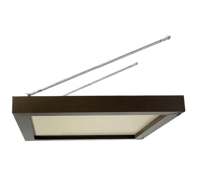
Door Canopies
Metallic Products’ door canopies offer a simple and cost-effective way to protect your building and the people who use it. Designed for durability and low maintenance, they provide reliable coverage from the elements while helping preserve your building systems and control long-term costs.
By reducing direct sun exposure at entry points, door canopies help lower energy usage and ease the load on HVAC systems. They also protect outdoor equipment from unnecessary wear, extending overall system lifespan.
Built with a sturdy 16-gauge galvanized frame, these canopies are engineered to withstand harsh weather conditions including strong winds and heavy snow loads. With a variety of sizes, colors, finishes, and single or double-door options available, they can be easily customized to match your building’s design.
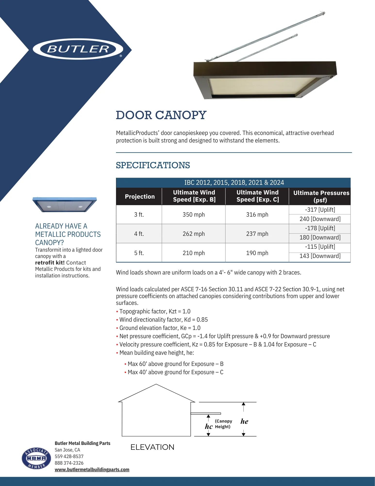
Specification Table
| Projection | Ultimate Wind Speed (Exp. B) | Ultimate Wind Speed (Exp. C) | Ultimate Pressure (psf) | Snow Load (psf) |
|---|---|---|---|---|
| 3 ft. | 350 mph | 316 mph | -317 (Uplift) / 240 (Downward) | Max = 144 psf |
| 4 ft. | 262 mph | 237 mph | -178 (Uplift) / 180 (Downward) | Max = 108 psf |
| 5 ft. | 210 mph | 190 mph | -115 (Uplift) / 143 (Downward) | Max = 86 psf |
NOTE: Wider canopies, more stringent loading requirements and customer engineering analysis available.
Wind loads shown are uniform loads on a 4′- 6″ wide canopy with 2 braces.
Wind loads calculated per ASCE 7-16 Section 30.11, using net pressure coefficients on attached canopies considering contributions from upper and lower surfaces.
- Topographic factor, Kzt = 1.0
- Wind directionality factor, Kd = 0.85
- Ground elevation factor, Ke = 1.0
- Net pressure coefficient, GCp = -1.4 for Uplift pressure & +0.9 for Downward pressure
- Velocity pressure coefficient, Kz = 0.85 for Exposure – B & 1.04 for Exposure – C
- Mean building eave height, he:
- Max 60′ above ground for Exposure – B
- Max 40’ above ground for Exposure – C

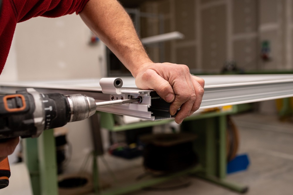
Construction
- Economical and attractive overhead protection from the elements
- Specifically designed for high wind load and heavy snow load areas
- 24-gauge flat soffit and integral gutter with rear-mounted drains
- 16-gauge galvanized internal frame for 3’ and 4’ projections, and 14-gauge galvanized internal frame for 5’ projection
- 5/8″ dia. rod end 4140 hot rolled annealed (HRA) [F.y = 125 ksi]
- 16-gauge telescoping support channels mount behind wall panel between girts, mounting clips and fasteners included
- 3/4″ dia. galvanized pipe hangers with adjustable rod ends
Finishes
- Galvalume steel
- Silicone polyester, Kynar® and powder coated finish options available in a wide range of colors
- Custom color matching
- Single color or two-tone (contrasting gutter/fascia and soffit)
Options
- Masonry mount (anchors by others)
- Downspouts
- Front mounted drains
- Light Kit
In Stock and Ready to Ship
Download the Complete Butler Door Canopy Spec Sheet
Need a Same Day Quote on Butler Door Canopies?
Download the Spec Sheet
Fill in the fields below to instantly download your spec sheet. A backup copy will also be sent to your email.